English
 中文简体
中文简体 Español
What Types of Relays Are Used in Automotive Applications?
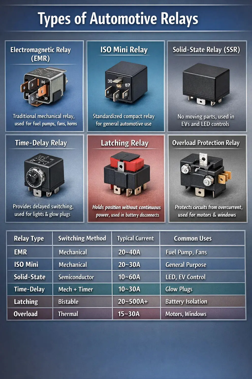
Automotive systems rely on several distinct types of relays, each designed to handle specific electrical tasks. The most common types include the electromagnetic relay (EMR), solid-state relay (SSR), time-delay relay, latching relay, overload protection relay, and the widely standardized ISO mini relay. In most modern passenger vehicles, you will encounter anywhere from 20 to over 60 individual relays distributed across fuse boxes, under the hood, and behind instrument panels. Understanding which automotive relay type does what — and where it belongs — is essential for diagnostics, upgrades, and proper vehicle electrical maintenance.
Each relay category carries its own electrical ratings, activation method, switching speed, and durability profile. Choosing the wrong type can result in premature failure, heat damage, or circuit faults that are notoriously difficult to trace. The sections below break down each type in detail, covering specifications, use cases, advantages, and common failure patterns.
Electromagnetic Relays (EMR): The Backbone of Automotive Electrical Systems
The electromagnetic relay is the most traditional and prevalent automotive relay type found in vehicles of all ages. Its operation is straightforward: a low-current control signal energizes a coil, which generates a magnetic field that physically pulls a set of metal contacts together, completing a higher-current circuit. When the control signal stops, a return spring opens the contacts again.
Typical automotive EMRs operate with a coil voltage of 12V DC, a coil resistance between 60Ω and 100Ω, and contact ratings ranging from 20A to 40A. Some heavy-duty versions used for starter circuits or trailer brake controllers handle up to 100A or more. The physical switching action produces an audible click, which is itself a useful diagnostic indicator — silence when you expect a click often points to a faulty coil, blown fuse, or loss of control voltage.
Four-Pin vs. Five-Pin EMR Configurations
EMRs in automotive contexts come in two primary pin configurations. The four-pin version handles a single circuit — it is either open or closed. The five-pin version adds a normally closed (NC) contact alongside the normally open (NO) contact, enabling more complex switching logic such as fan speed changeover or fuel pump control with a backup path.
- Pin 85 and 86 — coil terminals (control circuit)
- Pin 30 — common terminal (load circuit input)
- Pin 87 — normally open contact (closes when relay activates)
- Pin 87a — normally closed contact (five-pin only; opens when relay activates)
This standardized pin numbering follows the DIN 72552 standard, which most European and Japanese manufacturers adopted starting in the 1970s. American manufacturers began widespread adoption through the 1980s and 1990s, making ISO relay footprints nearly universal today.
Common Automotive Applications of EMRs
- Main fuel pump relay (typically rated 30A, controls the high-pressure fuel pump)
- Cooling fan relay (often 40A due to motor inrush current)
- Horn relay (protects the steering column switch from the high current demand of the horn)
- Starter motor relay and starter solenoid relay (used in sequence to energize the high-amperage starter circuit)
- AC compressor clutch relay
- Rear window defogger relay
- Main power relay for the ECU/PCM power supply circuit
ISO Mini Relay: The Standardized Workhorse of Modern Vehicles
The ISO mini relay — sometimes called the Bosch-style relay after its original developer — has become the default automotive relay format in production vehicles globally since the late 1980s. Its compact footprint (roughly 28mm × 28mm × 25mm), low cost, and interchangeability across manufacturers have made it the standard unit stocked in fuse boxes from budget economy cars to premium SUVs.
Contact ratings for the ISO mini relay are typically 20A to 30A, which covers the vast majority of auxiliary loads in a passenger car. For loads exceeding that threshold, automotive engineers step up to macro relays or contactor-style switching modules. ISO mini relays are available in both four-pin and five-pin configurations and are sold by virtually every major automotive parts manufacturer including Bosch, Hella, Omron, Tyco, and Duralast.
One key advantage of this relay type is its universal mounting: the relay plugs into a standard cavity on the fuse/relay box with no tools required. Replacement takes under 30 seconds, and a single relay block on many vehicles accommodates 8 to 20 individual relays of this form factor. Pricing for OEM-equivalent ISO mini relays typically falls between $3 and $15 USD, making them among the most cost-effective electrical components in any vehicle.
Solid-State Relays (SSR): Electronic Switching Without Moving Parts
Solid-state relays replace the mechanical contacts and electromagnetic coil of a traditional relay with semiconductor components — typically transistors, MOSFETs, thyristors (SCRs), or triacs. Because there are no moving parts, SSRs offer dramatically longer operational lifespans, silent operation, and faster switching speeds. While they are less common than EMRs in baseline automotive production, their presence has grown significantly in modern hybrid, electric, and high-end luxury vehicles where control precision and durability are prioritized over per-unit cost.
Key Advantages of SSRs in Automotive Environments
- Switching speed: SSRs can switch in microseconds compared to the 5–15ms mechanical delay of a standard EMR. This is critical in applications like ABS modulator control or variable valve timing solenoids.
- Lifespan: Mechanical relay contacts are typically rated for 100,000 to 500,000 switching cycles. Solid-state devices can exceed 10 million cycles with no wear.
- Vibration resistance: In off-road, racing, or high-vibration environments, mechanical contact bounce causes intermittent faults. SSRs eliminate this failure mode entirely.
- No contact arcing: Mechanical contacts generate an arc when breaking an inductive load. SSRs eliminate this, extending the life of connected components and reducing electromagnetic interference (EMI).
Limitations and Heat Management Considerations
SSRs are not without drawbacks. Unlike a mechanical relay, which has near-zero resistance when contacts are closed, an SSR has a small but real "on-state voltage drop" — typically 1V to 2V across the semiconductor junction. At 30A, that translates to 30–60W of heat dissipation that must be managed through proper heatsinking. In high-current automotive SSR applications, the thermal design is often more complex and expensive than the relay itself. Additionally, SSRs can fail in the "on" state (shorted), whereas mechanical relays more commonly fail open, which is generally the safer failure mode for many automotive circuits.
Automotive SSR applications include electronic throttle body control, electric power steering (EPS) modules, LED driver circuits, battery management systems in EVs, and HVAC blower speed controllers in premium vehicles.
Time-Delay Relays: Controlled Timing in Automotive Circuits
A time-delay relay (TDR) introduces a programmable or fixed delay between the input signal and the output switching action. In automotive systems, this is a practical necessity in several scenarios where immediate switching would cause problems or is simply undesirable.
There are two primary categories: on-delay relays, which wait a set period after receiving the input signal before closing the output circuit, and off-delay relays, which keep the output active for a defined time after the input signal is removed. Some vehicles use combination units that provide both functions within a single module.
Real-World Automotive Time-Delay Relay Examples
- Glow plug relay (diesel engines): Diesel vehicles use an on-delay relay to keep glow plugs energized for a set period (typically 2–10 seconds) after the ignition key is turned to the preheat position before allowing the engine to crank. This ensures combustion chamber temperatures are sufficient before injection begins.
- Interior lighting delay relay: When a car door closes, the dome light fades out over 10–30 seconds rather than cutting off immediately. This is controlled by an off-delay relay or, in modern vehicles, by a body control module (BCM) with an integrated timer.
- Cooling fan after-run relay: Many turbocharged and performance vehicles keep the radiator or turbo cooling fan running for 1–3 minutes after the engine shuts off to prevent heat soak damage. This is managed by an off-delay relay triggered by the ignition-off event.
- Wiper park delay relay: Intermittent wiper systems use a combination of time-delay circuitry and relay switching to control dwell time between wipe cycles.
Latching Relays: Holding State Without Continuous Power
A latching relay (also called a bistable relay or impulse relay) differs fundamentally from a standard electromagnetic relay in that it retains its switched state without requiring continuous coil current. Two brief pulses — one to set, one to reset — control the relay's position. Between pulses, the relay holds its last state mechanically, consuming zero power.
This makes latching relays ideal for automotive applications where battery drain is a concern and the switched circuit needs to remain active over extended periods. A typical automotive latching relay has a set/reset coil pulse requirement of 10–50ms, after which it holds position indefinitely without drawing coil current.
Where Latching Relays Appear in Vehicles
- Battery disconnect or isolation switches in electric and hybrid vehicles
- Central locking system actuators and door lock relays
- Auxiliary battery switching in start-stop systems
- Trailer supply sockets with memory function
- Electric sunroof or convertible top motor reversing circuits
In electric vehicles (EVs) specifically, high-voltage latching contactors — a heavy-duty variant of the latching relay concept — are used in the main battery pack disconnect circuit. These contactors can handle voltages of 400V to 800V and currents exceeding 500A, and they latch mechanically to avoid the catastrophic risk of an energized HV circuit losing its switching relay due to a coil failure.
Overload and Protection Relays: Preventing Electrical Damage
Overload protection relays monitor current flow through a circuit and automatically open the circuit when current exceeds a set threshold. Unlike fuses, which are one-time protective devices, overload relays are resettable — either manually or automatically after a cooldown period. In automotive design, these relays protect motors and actuators that may stall or experience excessive load without the driver being immediately aware.
Common installations include the power window motor circuit, which uses a self-resetting thermal protection relay that opens if the window glass encounters an obstruction and holds the motor stalled. Without this protection, a stalled window motor can draw 15–20A continuously — far above its rated running current of 3–5A — and cause winding burnout within seconds. Similarly, the blower motor resistor circuit on HVAC systems often incorporates thermal protection to prevent overheating during blocked-airflow conditions.
Modern vehicles increasingly integrate overload protection logic directly into smart power modules or body control modules (BCMs), rather than using discrete relay-based protection. However, standalone overload relays remain common in commercial vehicles, fleet trucks, and aftermarket accessory installations where the additional cost of integrated protection is not justified.
Flasher Relays: Timing the Turn Signal and Hazard Circuits
The flasher relay is a specialized automotive relay type that generates a repeating on/off cycle to produce the blinking action of turn signals and hazard lights. Traditional thermal flashers used a bi-metallic strip that heated and cooled cyclically to interrupt the circuit. Modern electronic flashers use an oscillator circuit and solid-state components to achieve the same effect with greater reliability and consistency.
Federal Motor Vehicle Safety Standards (FMVSS 108) require turn signal flash rates between 60 and 120 flashes per minute for legal road use in the United States, with similar requirements in the EU under ECE Regulation 6. The standard flash rate for most OEM flasher relays is calibrated to approximately 90 flashes per minute under normal load conditions.
A well-known diagnostic behavior of thermal flashers is that their flash rate changes when bulb wattage changes. Adding a trailer with additional lighting loads, or replacing incandescent bulbs with LEDs (which draw far less current), causes the flasher to either hyper-flash (flash too fast) or stop flashing altogether. This behavior was used as a built-in indicator of a burned-out bulb on older vehicles. For LED conversions, a load-independent electronic flasher or an inline resistor must be used to maintain correct flash rates.
High-Power Contactors: Automotive Relays for Heavy-Duty Applications
When current demands exceed what standard ISO mini relays or even larger macro relays can handle, automotive engineers turn to contactors — essentially industrial-grade relays designed for very high current switching. In conventional 12V vehicles, contactors appear in applications like winch motor control, vehicle-mounted crane circuits, and military or emergency vehicle power distribution.
In electric and hybrid vehicles, high-voltage contactors are mission-critical components. The main battery contactor in a typical BEV (Battery Electric Vehicle) must handle pack voltages of 400V to 800V and sustained currents of 300A to 600A, with peak current capability during fast charging or hard acceleration exceeding 1,000A in some performance platforms. These are not passive relay contacts — they incorporate arc suppression systems, pre-charge circuits to limit inrush current, and often welding detection logic to identify if contacts have fused together.
Contactor Safety Features in EV Battery Systems
- Pre-charge contactor: A small resistor and auxiliary contactor are used to slowly charge the inverter capacitors before the main contactor closes, preventing the destructive current spike that would otherwise occur.
- Contact welding detection: The BMS checks whether contacts open correctly after a disconnect command. Welded contacts create a critical safety fault that disables the vehicle.
- Sealed gas-filled housing: Many HV contactors are filled with hydrogen gas, which has superior arc-quenching properties compared to air, enabling reliable switching at high voltages.
- Dual contactor design: Most BEV battery packs use separate positive and negative main contactors, both of which must close in sequence and open simultaneously on shutdown to safely isolate the high-voltage bus.
Automotive Relay Comparison Table
The table below summarizes the key specifications and use cases across the primary automotive relay types discussed in this article.
| Relay Type | Switching Method | Typical Current Rating | Lifespan (cycles) | Common Applications |
|---|---|---|---|---|
| Electromagnetic (EMR) | Mechanical contacts | 20–40A (12V) | 100K–500K | Fuel pump, cooling fan, horn, ECU power |
| ISO Mini Relay | Mechanical contacts | 20–30A (12V) | 100K–500K | General purpose fuse box use |
| Solid-State (SSR) | Semiconductor | 10–60A | 10M+ | EPS, EV control modules, LED drivers |
| Time-Delay Relay | Mechanical + timer | 10–30A | 100K–500K | Glow plugs, after-run fans, lighting |
| Latching Relay | Mechanical bistable | 20–500A+ | 100K–1M | Battery isolation, door locks, EV contactors |
| Flasher Relay | Thermal or electronic oscillator | 5–15A | Varies widely | Turn signals, hazard lights |
| HV Contactor | Sealed mechanical | 300A–1000A+ | 50K–200K | EV battery pack isolation, fast charging |
How to Identify a Failing Automotive Relay
Relay failure is one of the more deceptive fault patterns in automotive electrical diagnosis because the symptoms often mimic other component failures. A failed fuel pump relay produces the same symptoms as a dead fuel pump. A failed cooling fan relay looks exactly like a faulty fan motor. Knowing how to isolate the relay from the rest of the circuit saves significant diagnostic time.
Symptoms of a Faulty Automotive Relay
- No click sound when the control circuit is activated — suggests the coil is not receiving voltage or has an open winding
- Continuous clicking in a chattering pattern — often caused by low battery voltage causing the coil to repeatedly activate and drop out
- Correct click but no output — indicates the contacts have burned or corroded open despite the coil working correctly
- Circuit stays on permanently — indicates welded contacts (common in relays that switch high-inrush loads without adequate contact ratings)
- Intermittent operation — often caused by oxidized contacts or a cracked coil winding that makes inconsistent contact under vibration or heat
Quick Relay Testing Methods
- Swap test: Locate an identical relay nearby on the fuse block and swap positions. If the fault follows the relay, the relay is faulty. This works only if the replacement relay has the same part number or is confirmed compatible.
- Coil resistance test: Remove the relay and measure resistance between coil pins (85 and 86). A healthy 12V automotive relay coil typically reads between 60Ω and 100Ω. Open circuit (infinite resistance) or very low resistance indicates a damaged coil.
- Contact continuity test: Apply 12V directly to the coil terminals and use a multimeter in continuity mode to verify that pin 30 and pin 87 connect when the relay is energized.
- Voltage drop test: With the relay in circuit and energized, measure voltage drop across pins 30 and 87. A drop exceeding 0.3V under load indicates high-resistance or corroded contacts.
Selecting the Right Automotive Relay for Aftermarket and Custom Installations
When adding electrical accessories to a vehicle — auxiliary lighting, a winch, an aftermarket air compressor, or a supplemental battery system — selecting the correct automotive relay type and specification is as important as the wiring itself. Undersized relays fail quickly. Oversized relays often cost more without delivering any practical benefit for smaller loads.
Relay Sizing Guidelines
- Always size the relay contact rating to handle at least 125% of the maximum continuous current of the load. A 20A load should use a 25A or 30A relay minimum.
- For inductive loads (motors, solenoids, compressors), account for inrush current — which can be 3 to 7 times the rated running current — when selecting relay contacts and any protective fusing.
- Use a five-pin relay when you need a changeover function (for example, switching between two load paths based on a single control signal).
- If the relay will be mounted in an exposed location subject to moisture, road splash, or temperature extremes, use a sealed or weatherproof automotive relay rated for IP54 or higher.
- For LED lighting installations where flash rate accuracy matters, always select an electronic flasher relay rated for low-current loads rather than repurposing a thermal unit calibrated for incandescent bulbs.
Relay quality is also worth considering. Budget relays from unverified sources often use contact materials that corrode or pit faster than OEM-grade equivalents. For any safety-critical circuit — fuel supply, engine cooling, or braking — use relays from verified manufacturers such as Bosch, Omron, TE Connectivity, or Hella. The cost difference between a $3 economy relay and a $10 OEM-grade relay is negligible compared to the diagnostic labor of tracing an intermittent fault caused by relay failure six months into service.