 English
 中文简体
中文简体 Español
What Is Relay Wiring and Why It Matters
Relay wiring is the process of connecting an electromechanical or solid-state relay into a circuit so that a low-power control signal can switch a much larger load safely and reliably. In plain terms, a relay acts as an electrically operated switch: a small current energizes a coil, which moves a mechanical armature or triggers a semiconductor junction, completing or breaking a separate high-power circuit. Getting the wiring right is the difference between a system that works for years and one that fails dangerously within hours.
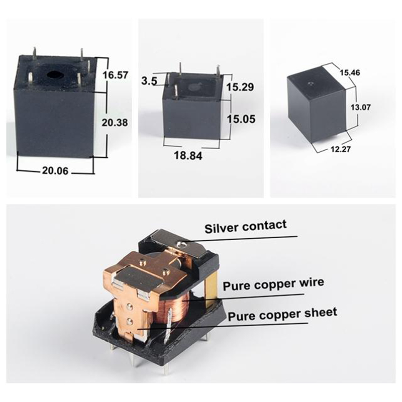
The practical importance is easy to underestimate. A typical automotive relay coil draws only 150–200 mA from a microcontroller or switch, yet the relay's output contacts can handle 30 A at 12 V DC — more than enough for headlights, fuel pumps, or cooling fans. Without a relay in that circuit, the thin wiring to a dash switch would overheat and become a fire risk. Correct relay wiring eliminates that hazard while also protecting sensitive electronics upstream.
This guide covers every major aspect of relay wiring: pin identification, circuit diagrams for common configurations, wire gauge selection, suppression of voltage spikes, troubleshooting, and real-world examples from automotive, industrial, and residential applications. Whether you are wiring a single accessory relay in a vehicle or designing a multi-relay control panel for machinery, the principles here apply directly.
Understanding Relay Pin Configurations Before You Wire Anything
Before connecting a single wire, you must identify every pin on your relay. Mistakes at this stage cause burned contacts, blown fuses, and damaged loads. Most relays follow standardized numbering, but physical layouts vary by form factor.
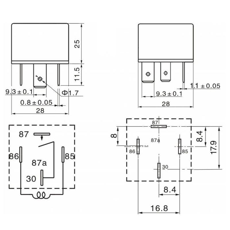
The Standard 5-Pin Automotive Relay (ISO 280 / Bosch Mini)
The most common relay in vehicle wiring harnesses worldwide is the 5-pin mini relay conforming to the ISO 280 footprint. Its pins are numbered as follows:
| Pin Number | Function | Typical Connection |
|---|---|---|
| 85 | Coil negative (−) | Ground / chassis |
| 86 | Coil positive (+) | Control switch or ECU output |
| 30 | Common (COM) | Fused battery positive |
| 87 | Normally Open (NO) | Load (device to be powered) |
| 87a | Normally Closed (NC) | Backup circuit or unused |
A 4-pin relay omits the 87a (NC) terminal entirely. It is adequate whenever you only need the circuit to close when energized and have no need for a normally closed backup path. Most basic relay wiring jobs — fog lights, horns, auxiliary fans — use 4-pin relays for this reason.
DIN Rail and Industrial Relay Terminal Layouts
Industrial relays mounted on DIN rail — such as the Finder 40 series or the Phoenix Contact PLC-RSC family — use a different terminal labeling convention. Coil terminals are labeled A1 (positive) and A2 (negative). Contact sets are numbered in pairs: 11/14 for the first pole COM/NO, 11/12 for COM/NC, and so on for multi-pole versions. Always consult the relay's datasheet pinout diagram before wiring; a mislabeled terminal on a 24 V DC industrial relay can inject voltage directly into a PLC input card and destroy it.
Core Relay Wiring Diagrams Explained
There are several fundamental wiring arrangements used across industries. Understanding each one gives you the flexibility to handle almost any relay wiring task.
Basic Single-Relay Wiring Circuit (Normally Open)
This is the foundational relay wiring configuration. The circuit has two entirely separate loops sharing only the relay body:
- Control loop: Battery (+) → fuse (1–5 A) → control switch → relay pin 86 → relay pin 85 → ground. When the switch closes, current flows through the coil and the relay energizes.
- Load loop: Battery (+) → fuse (sized to the load) → relay pin 30 → relay pin 87 → load device → ground. This loop is only complete when the relay is energized.
The fuse in the load loop must be rated at no more than 125% of the load's normal operating current and placed as close to the battery as physically possible — ideally within 30 cm. This is not optional; it is a fundamental wiring safety requirement.
Self-Latching Relay Wiring
A self-latching (or holding) relay circuit keeps the relay energized after a momentary trigger is released. This is used in starter circuits, alarm systems, and any application where you want a single button press to maintain a state. The wiring adds one additional wire: a feedback wire from relay pin 87 back to relay pin 86, in parallel with the original trigger switch. Once the relay closes, it feeds its own coil power through the NO contact, holding itself on. A separate normally closed (NC) reset switch in series with the coil circuit breaks the latch when needed.
Relay Wiring for Reversing Motor Direction (H-Bridge with Relays)
Using four SPDT relays in an H-bridge configuration allows a DC motor to run in both directions. In position A, relays 1 and 4 energize, connecting the motor in one polarity. In position B, relays 2 and 3 energize, reversing polarity. Never energize both sets simultaneously — this creates a direct short across the power supply. Mechanical or software interlocking is mandatory in any relay-based reversing wiring scheme. A common implementation uses a relay whose NC contact wires into the coil circuit of the opposing relay, providing true hardware interlock.
Using the Normally Closed Contact in Relay Wiring
The NC contact (pin 87a on a 5-pin relay) is closed when the relay is de-energized and open when energized. This is useful for fail-safe wiring: connect your critical load to the NC contact, and it will remain powered during normal operation but shut off when the relay coil is energized — for example, by a fault detection signal. Fire suppression panels, conveyor emergency stops, and generator transfer switches frequently use NC relay wiring for exactly this reason.

Choosing the Right Wire Gauge for Relay Wiring
Wire selection is one of the most consequential decisions in relay wiring. Use wire that is too thin, and resistance causes voltage drop and heat. Use wire that is too thick, and the installation becomes unnecessarily stiff, expensive, and difficult to route.
| Circuit Type | Typical Current | Recommended AWG | Metric Equivalent |
|---|---|---|---|
| Relay coil control wire | 0.1–0.5 A | 20–22 AWG | 0.5–0.75 mm² |
| Light accessories (LEDs, signals) | 1–5 A | 18 AWG | 0.75–1.0 mm² |
| Headlights, fans, small motors | 10–20 A | 14–16 AWG | 1.5–2.5 mm² |
| High-current loads (winches, compressors) | 30–50 A | 10–12 AWG | 4.0–6.0 mm² |
For runs longer than 3 meters, drop one wire gauge size (increase the conductor area) to compensate for resistance-related voltage drop. A voltage drop exceeding 3% of supply voltage will cause reliability issues, particularly with relay coils that have a minimum pull-in voltage of typically 70–80% of rated coil voltage.
Always use stranded wire rather than solid-core wire in relay wiring applications subject to vibration — automotive and industrial environments both qualify. Stranded wire resists fatigue cracking at terminals far better than solid wire under repeated movement. Use ring terminals or properly crimped spade connectors; twisted wire shoved under a screw terminal is a failure waiting to happen.
Flyback Diodes and Voltage Spike Suppression in Relay Wiring
This is arguably the most overlooked element of relay wiring, and omitting it destroys electronics. When a relay coil is de-energized, the magnetic field collapses and generates a reverse voltage spike that can reach 50–100 V on a 12 V system. This transient, if not suppressed, travels back through the control circuit and kills transistors, microcontroller outputs, and MOSFETs.
Installing a Flyback (Freewheeling) Diode
The standard fix is a flyback diode wired in reverse-bias across the relay coil terminals — anode to pin 85, cathode to pin 86. During normal operation, the diode is reverse-biased and carries no current. When the coil de-energizes, the spike forward-biases the diode, giving the stored inductive energy a safe path to dissipate as heat rather than a spike. A 1N4007 diode (1 A, 1000 V reverse breakdown) is more than adequate for most relay coil suppression. Solder it directly across the relay's coil terminals or as close to them as the layout allows.
One trade-off: a plain flyback diode slows relay release time because the collapsing energy dissipates more gradually. In applications where fast release is critical — such as relay-controlled brake circuits — a Zener diode (typically 24 V for a 12 V relay) in series with a standard diode provides faster energy dissipation while still clamping the spike to a safe level.
Snubber Circuits for AC Relay Wiring
In AC relay wiring, a simple diode will not work because current alternates direction. Instead, use an RC snubber network (a resistor and capacitor in series) wired across the coil. A common starting value is 100 Ω in series with 0.1 µF, rated for at least twice the AC line voltage. The snubber absorbs the inductive spike by converting it to a small amount of heat across the resistor. MOV (Metal Oxide Varistor) components provide additional protection against line transients in 120 V and 240 V relay wiring installations.
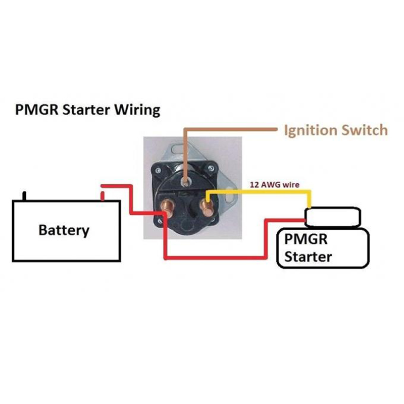
Automotive Relay Wiring: Step-by-Step for Common Applications
Automotive relay wiring accounts for the majority of DIY relay projects. Here is a complete walkthrough for the most common scenario: wiring a relay to power auxiliary lights from a switched 12 V trigger.
Materials Needed
- One 12 V 30/40 A 5-pin ISO 280 relay
- One inline fuse holder with appropriately rated fuse (calculate load amps × 1.25, round up to next standard fuse size)
- 16 AWG red wire (load positive), 16 AWG black wire (grounds), 18 AWG trigger wire
- Female spade terminals sized for the relay pins (6.3 mm for ISO 280)
- Ratchet crimping tool, heat-shrink tubing, wire stripper
- One 1N4007 diode for spike suppression
Wiring Procedure
- Disconnect the negative battery terminal before starting any relay wiring work.
- Run a red wire from the battery positive terminal through the fuse holder to relay pin 30. Keep this wire as short as practical and route away from heat sources.
- Run a red wire from relay pin 87 to the positive terminal of your auxiliary lights.
- Run a black wire from relay pin 85 to a clean chassis ground point. Use a star washer under the ring terminal to ensure good metal-to-metal contact.
- Run the 18 AWG trigger wire from your control switch or ignition-switched source to relay pin 86. This wire only carries coil current, so 18 AWG is sufficient for any run under 5 meters.
- Solder the 1N4007 diode across pins 85 and 86: cathode (stripe end) to pin 86, anode to pin 85.
- Connect the negative wire from your auxiliary lights to chassis ground, ideally at the same ground point used in step 4.
- Reconnect the battery, activate the control switch, and verify the relay clicks and the lights illuminate. Check for warm connections after 5 minutes of operation — heat indicates high resistance at a terminal.
This same relay wiring procedure applies to electric fans, air horns, compressors, and any accessory drawing more than 5–8 A that you would otherwise run through a standard dash switch.
Industrial and Control Panel Relay Wiring Practices
Industrial relay wiring involves higher voltages, greater current demands, and stricter safety standards than automotive work. A relay control panel in a manufacturing environment may incorporate dozens of relays controlling motors, solenoid valves, heating elements, and indicator lights — all wired to a PLC or hardwired logic system.
24 V DC Control Voltage as the Industry Standard
Most modern industrial relay wiring uses 24 V DC for the control circuit, regardless of the load voltage (which may be 120 V AC, 240 V AC, or 480 V AC three-phase). The 24 V DC control standard improves safety for technicians, is directly compatible with PLC output cards, and reduces the risk of electrical shock during commissioning and maintenance. Relay families like the Omron MY series, the Finder 55 series, and the Siemens 3RH/3RT contactors are all designed around this control voltage standard.
Relay Wiring in Ladder Logic and Control Diagrams
Industrial relay wiring is specified using ladder logic diagrams (also called ladder diagrams or LD). Each rung of the ladder represents a control path. Relay coils are drawn as circles at the right side of each rung; relay contacts (NO or NC) are drawn as parallel or crossed lines in series along each rung. When reading a relay wiring ladder diagram, identify the coil designation (e.g., CR1 for Control Relay 1) and then find all contacts bearing that same designation throughout the diagram — those are the contacts that change state when CR1 energizes. This cross-reference is essential for tracing complex relay wiring logic without error.
Terminal Block Wiring for Relay Panels
In panel relay wiring, individual wires from relays, PLCs, and field devices terminate at DIN-rail-mounted terminal blocks. Each terminal gets a unique wire number, marked with a ferrule sleeve (end-sleeve crimp) and printed label. This system allows any wire in the panel to be traced in under 60 seconds using a wiring diagram, which is critical for maintenance in a production environment. The Phoenix Contact PTFIX and Weidmüller W-Series terminal systems are widely used for relay panel wiring in North America and Europe.
Use ferrule crimps on all stranded wires entering screw terminals. Bare stranded wire in a screw terminal tends to cold-creep over time, loosening the connection and increasing resistance. A loose relay wiring connection in a motor starter circuit can cause intermittent motor operation, overheating, and eventual failure of the relay contacts.
Solid-State Relay Wiring Versus Electromechanical Relay Wiring
Solid-state relays (SSRs) use semiconductor switching elements (typically TRIACs for AC loads or MOSFETs for DC loads) with optical isolation between control and load circuits. They have no moving parts, which means silent operation and theoretically longer service life in high-cycle applications. However, SSR wiring requires attention to several factors that differ significantly from electromechanical relay wiring.
Heat Management Is Mandatory in SSR Wiring Installations
An electromechanical relay has a contact resistance so low it generates negligible heat during conduction. An SSR's semiconductor switch has a finite on-state voltage drop — typically 1.0–1.5 V for a TRIAC-based AC SSR. At 25 A load current, that's up to 37.5 W of heat dissipated in the SSR package. Without adequate heatsinking, the SSR will overheat and fail, often silently in the shorted position — leaving the load permanently on. SSR wiring must always include a properly sized heatsink, with thermal compound applied between the SSR and heatsink. A common rule of thumb is 1°C/W thermal resistance for every 2 A of load current when ambient temperature is 25°C.
SSR Control Input Wiring
Most DC control input SSRs accept a control voltage range of 3–32 V DC, making them directly compatible with both 3.3 V and 5 V microcontroller outputs such as Arduino, Raspberry Pi, and ESP32 boards. This eliminates the need for a transistor driver stage that electromechanical relay modules sometimes require. Connect the SSR's control positive to the microcontroller digital output pin and the control negative to the MCU ground. Polarity matters — reverse connection will not activate the SSR and may damage it.
Leakage Current Issues in SSR Wiring
SSRs have a small off-state leakage current, typically 1–10 mA, that flows through the load even when the SSR is commanded off. For resistive loads like heaters, this is negligible. For low-power LED indicator lights wired through an SSR, this leakage current may be enough to keep the LED faintly lit when it should be off. The solution is a bleed resistor wired in parallel with the load, providing the leakage current an alternate path to ground. A 100 kΩ, 2 W resistor across the load output is usually sufficient.
Relay Wiring for Time-Delay and Sequencing Applications
Standard relays switch instantaneously. Time-delay relays (also called timer relays) introduce a programmable delay between the control signal and the contact action. There are four primary timing modes used in relay wiring:
- On-delay (TON): Contacts switch after a set delay following coil energization. Used for motor soft-start sequences and HVAC compressor delays.
- Off-delay (TOF): Contacts remain in the energized position for a set time after the coil is de-energized. Used for engine cooling fans that must run after shutdown.
- Interval timer: Contacts close for a fixed time period after trigger, then open regardless of whether the trigger remains. Used in timed solenoid valve relay wiring for irrigation systems.
- Repeat cycle (flasher): Contacts alternate open and closed at a set frequency. Used in warning light relay wiring, sequencing circuits, and pump alternator control panels.
Timer relay wiring follows the same basic pin conventions as standard relays, with the addition of timing adjustment potentiometers or DIP switches on the relay body. Some units, such as the Omron H3CR series, combine multiple timing modes in a single unit selectable by DIP switch, making them versatile for industrial relay wiring panels.
Troubleshooting Relay Wiring Problems
When a relay circuit fails, a systematic approach saves hours of frustration. Most relay wiring faults fall into one of five categories.
Relay Does Not Energize
Measure voltage between pin 86 and pin 85 with the control switch activated. You should see rated coil voltage (12 V on a 12 V relay, 24 V on a 24 V relay). If voltage is absent, the fault is in the control circuit — check the control switch, fuse, and trigger wire. If voltage is present but the relay does not click, the coil is open-circuit; replace the relay. A burned coil often has a resistance reading of infinity on a multimeter set to the Ω range; a healthy 12 V relay coil typically measures 70–100 Ω.
Relay Energizes but Load Does Not Operate
The relay clicks, confirming coil circuit operation. Now check the load circuit. Measure voltage at pin 30 (should be battery voltage). Measure voltage at pin 87 with relay energized (should equal pin 30 minus a very small contact drop, typically under 0.1 V). If pin 87 shows no voltage, the relay's NO contacts are burned open — replace the relay. If pin 87 shows voltage but the load does not operate, the fault is in the load wiring or the load device itself.
Relay Chatters or Buzzes
Relay chattering — rapid cycling of the contacts — usually indicates insufficient coil voltage. This happens when the supply voltage at the relay is too low to fully latch the armature. Check for voltage drop in the coil supply wire, a failing control switch with high contact resistance, or an undersized wire causing excessive resistance. Alternatively, the relay may be rated for a different coil voltage than the supply. A 24 V relay receiving only 12 V will chatter continuously. Verify the relay's coil voltage rating on the body label before installation.
Relay Contacts Arcing and Burning
Contact arcing burns pits into the contact surfaces, increasing resistance and eventually welding contacts together or causing open-circuit failure. The causes are almost always one of the following: switching a load beyond the relay's rated contact current, switching a highly inductive load (motor or solenoid) without arc suppression, or switching too frequently. The relay contact rating for DC loads is significantly lower than for AC loads due to the absence of a natural zero-crossing to extinguish the arc. A relay rated 30 A at 12 V AC may only be rated 5–10 A at 12 V DC — always check the DC contact rating specifically when wiring DC load circuits.
Intermittent Operation
Intermittent relay operation that cannot be reproduced on the bench almost always traces back to a loose terminal, corroded connector, or vibration-induced wire fatigue. Apply dielectric grease to all relay socket connections in automotive applications. In industrial environments, torque all screw terminals to the manufacturer's specified value (typically 0.5–0.8 N·m for 2.5 mm² terminals) and re-torque after the first 24 hours of operation as the conductor material settles under the screw.
Common Relay Wiring Mistakes to Avoid
Experience from relay installations across thousands of vehicles and industrial systems reveals the same errors appearing repeatedly. Avoiding them from the start saves rework, component replacement, and potentially dangerous failures.
- No flyback diode on the coil circuit. Every transistor-controlled relay circuit needs suppression. If you are driving the relay coil from a BJT, MOSFET, or microcontroller, omitting the diode will eventually destroy the switching component.
- Fuse placed on the wrong side of the relay. The fuse protects the wire, not the load. Place the fuse as close to the power source as possible, before any length of unprotected wire.
- Sharing a ground return with high-current loads. Running the relay coil ground through the same return wire as a high-current load introduces noise and potential voltage on the control circuit. Always give the coil a dedicated ground path.
- Using a relay with the wrong contact rating for DC loads. AC-rated contact currents do not translate to DC. Check the relay datasheet for DC contact ratings explicitly.
- Twisting wire ends instead of using proper crimped terminals. Twisted wire under a spade terminal or screw loosens, corrodes, and fails. Invest in a quality ratcheting crimper and correctly sized terminals.
- Ignoring inrush current. Motors, capacitive loads, and incandescent bulbs draw significantly more current at startup than during steady-state operation. A motor may draw 6–10× its running current for the first few cycles. Size relay contacts for inrush, not just running current.
- Mounting the relay in a high-heat location. Ambient temperature directly affects both coil pull-in voltage and contact rating. A relay rated for 30 A at 25°C may only handle 20 A at 85°C. Keep relays away from exhaust systems, engine blocks, and industrial heating equipment.
Relay Wiring for Specific Real-World Applications
Electric Cooling Fan Relay Wiring
An electric cooling fan on a vehicle draws typically 15–25 A at full speed. The engine coolant temperature sensor or ECU provides a 12 V switched output when coolant exceeds a threshold, typically 95–100°C. This output triggers the relay coil, closing the high-current circuit to the fan motor. A second relay is often added in the same circuit to provide a manual override from a dash switch, wired so either the ECU signal or the manual switch can energize the relay coil independently. Both signals feed into a diode OR gate at pin 86 to prevent backfeeding.
Home Generator Transfer Switch Relay Wiring
A manual or automatic transfer switch uses relays (or contactors in high-current installations) to disconnect the utility grid supply and connect generator power to the home panel. The relay wiring must include a mechanical or electrical interlock ensuring the utility and generator supplies can never be simultaneously connected — this is a safety requirement under NEC Article 702 in the United States. Electrically interlocked relays use NC contacts of each relay in the coil circuit of the other, making it physically impossible to energize both relays at the same time. This is the same principle as the H-bridge interlock described earlier, scaled to line voltage.
Arduino / Raspberry Pi Relay Wiring for Home Automation
Low-voltage microcontroller relay wiring has become common in DIY home automation. Commercial relay modules designed for Arduino and Raspberry Pi use an optocoupler between the microcontroller signal pin and the relay coil transistor driver, providing isolation. These modules typically accept 5 V control signals and include the flyback diode on-board. However, most off-the-shelf relay modules are rated for 10 A at 250 V AC — sufficient for low-power household loads but not for anything above 1200 W on a 120 V circuit or 2400 W on a 240 V circuit. For higher loads, use the microcontroller relay module to control a larger, properly rated DIN-rail relay rather than running high current directly through the module's contacts.


