 English
 中文简体
中文简体 Español
What a Relay Actually Does — The Short Answer
A relay is an electrically operated switch. It uses a small electric current to control a much larger one — without the two circuits ever physically touching. That's the core idea, and everything else flows from it.
Think of it this way: you want to turn on a powerful motor, but the switch on your wall can only handle a tiny amount of current. A relay sits in the middle. Your wall switch sends a small signal to the relay, and the relay does the heavy lifting — closing or opening the high-power circuit on your behalf. The relay acts as a gatekeeper between a low-power control signal and a high-power load.
This principle is why relays appear in cars, industrial machines, home appliances, and electronics of every size. Once you understand what a relay does, you start seeing them everywhere.
The Basic Parts of a Relay and How They Work Together
A traditional electromagnetic relay — the most common type — has just a handful of components, and each one has a clear job.
The Coil
When current flows through the coil, it generates a magnetic field. This is the "input" side of the relay — the part connected to your low-power control circuit. Typical coil voltages range from 5V to 24V DC, making them easy to drive from microcontrollers, sensors, or logic boards.
The Armature and Spring
The magnetic field attracts a movable metal arm called the armature. A spring normally holds the armature in its resting position. When the coil energizes, the magnet pulls the armature toward it, physically moving the switch contacts.
The Contacts
The contacts are the actual switching points — small metal pads that either touch (closed circuit) or separate (open circuit). Most relays have at least one set of contacts rated for much higher voltages and currents than the coil side. A typical general-purpose relay might switch up to 250V AC and 10 amps, while its coil only needs 12V DC and about 150 milliamps to operate.
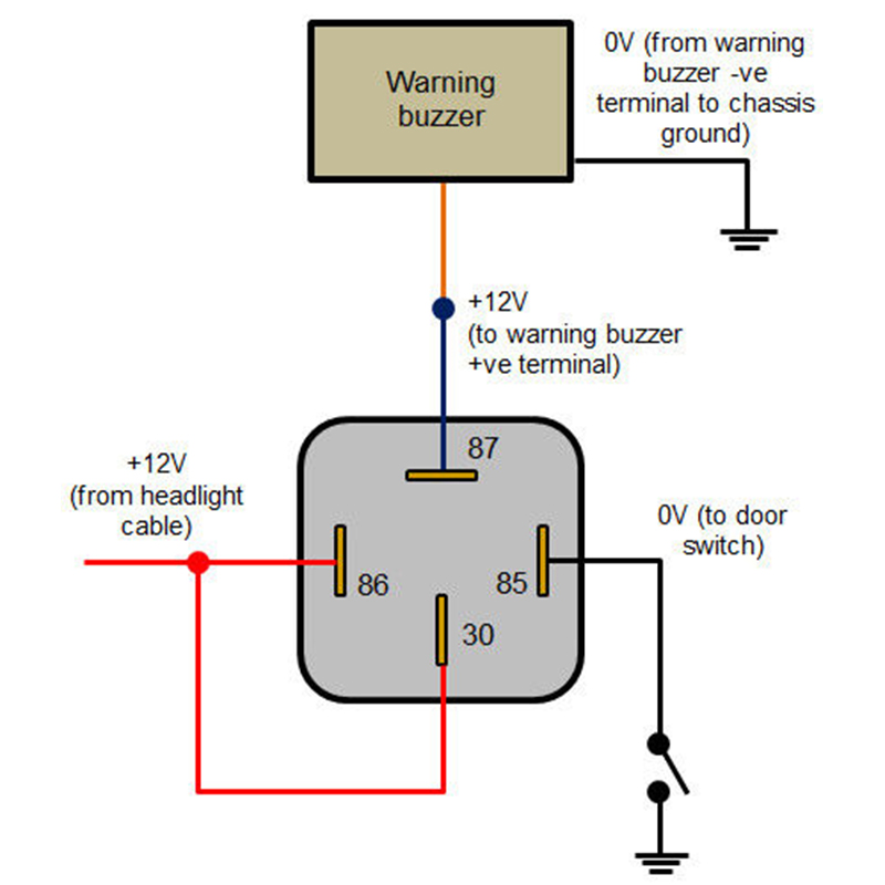
Here's how the three contact types are usually labeled:
| Terminal Name | Full Name | Behavior When Relay Is Off | Behavior When Relay Is On |
|---|---|---|---|
| COM | Common | The shared terminal — always connected | The shared terminal — always connected |
| NC | Normally Closed | Connected to COM | Disconnected from COM |
| NO | Normally Open | Disconnected from COM | Connected to COM |
Most practical wiring uses the NO terminal — the load only gets power when the relay is actively triggered. The NC terminal is useful for fail-safe setups where you want something running by default and only want to cut power when triggered.
Why Electrical Isolation Matters — And Why Relays Provide It
One of the most important things a relay does — and one that often goes unmentioned in simple explanations — is provide galvanic isolation between the control circuit and the load circuit. The two sides have no electrical connection. Only a magnetic field bridges them.
Why does that matter in real life?
- A microcontroller or sensor operating at 3.3V or 5V can safely switch a 240V AC mains circuit — with no risk of the high voltage destroying the low-voltage electronics.
- Noise and voltage spikes on the load side do not travel back into sensitive control circuitry.
- Ground loops between different parts of a system are broken, which reduces interference in audio or instrumentation equipment.
- Safety regulations in industrial settings often require physical isolation between operator controls and dangerous voltages — a relay satisfies this requirement mechanically.
This isolation feature is one reason relays remain in use even when transistors and solid-state devices can technically do the same switching job. When true electrical isolation is a requirement, a mechanical relay is often the simplest and most reliable solution.
Everyday Places Where Relays Are at Work Right Now
Relays are not abstract or exotic. They sit inside equipment you use every day, doing their switching quietly and reliably.
Inside Your Car
Modern vehicles use dozens of relays. The starter relay is one of the most critical — when you turn the ignition key or press the start button, a small signal from the ignition switch activates a relay, which then closes the circuit to deliver hundreds of amps to the starter motor. Running that kind of current through a dashboard switch would melt the wiring immediately. The relay handles it safely, tucked away in the fuse box under the hood.
Other car relays control headlights, cooling fans, fuel pumps, air conditioning compressors, and horn circuits. The fuel pump relay in particular is a common failure point — when it fails, the engine won't start even though everything else checks out, which is why knowing what a relay does helps with basic diagnosis.
Home Appliances
Your washing machine, refrigerator, dishwasher, and air conditioner all use relays. In a refrigerator, a start relay helps kick the compressor motor into operation — it provides an extra boost of current at startup, then drops out once the motor is running. This relay is small enough to hold in your hand, yet it cycles on and off thousands of times over the appliance's lifetime.
HVAC thermostats use relays to switch the compressor, fan, and heating elements. When your thermostat "clicks," you're hearing the relay armature snap into position.
Industrial and Commercial Equipment
In factories, large relay variants called contactors switch motors, lighting banks, and heating systems rated for tens or hundreds of kilowatts. Protective relays monitor electrical systems for faults — overcurrent, ground faults, phase imbalance — and disconnect equipment within milliseconds when something goes wrong. These protective relays are why a short circuit in one part of a building doesn't take out the entire facility.
DIY Electronics and Arduino Projects
Relay modules for microcontrollers are widely available for under $2 each. A common use case: an Arduino or Raspberry Pi reads a temperature sensor, and when the temperature exceeds a threshold, it triggers a relay to switch on a fan or heater connected to household mains power. The microcontroller never touches the mains voltage — the relay keeps it completely separate.
Types of Relays — Not All Relays Work the Same Way
The electromagnetic relay described above is the classic design, but several other relay types exist, each suited to different situations.
Solid-State Relay (SSR)
A solid-state relay performs the same function — switching a load circuit from a control signal — but uses semiconductor components instead of moving parts. There is no coil, no armature, no click. SSRs switch silently, have no mechanical wear, and can operate at much higher speeds than mechanical relays. They're common in temperature control systems and anywhere that frequent switching would wear out mechanical contacts. The trade-off: they generate more heat and typically cannot switch AC and DC interchangeably the way a mechanical relay can.
Reed Relay
A reed relay uses a small glass capsule containing two thin metal reeds in an inert gas atmosphere. When a magnetic field is applied — either from a coil around the capsule or an external magnet — the reeds attract each other and make contact. Reed relays are fast, small, and very sensitive. They appear in test equipment, telecommunications, and security sensors (the kind on door and window frames use a permanent magnet and a standalone reed switch rather than a coil, but the principle is identical).
Latching Relay
A standard relay returns to its resting state the moment the coil loses power. A latching relay stays in whichever position it was last set — it requires a second pulse to change state. This is useful when you need the relay to hold its position without continuously drawing current, such as in energy metering, smart grid switching, or battery-powered devices where keeping a coil energized would drain the power source.
Time-Delay Relay
A time-delay relay switches its contacts after a preset time interval — either on-delay (waits before closing) or off-delay (stays closed for a period after the signal stops). These appear in motor starter circuits to prevent all machines from starting simultaneously, in lighting systems that keep lights on for a fixed time after a button press, and in HVAC systems to sequence equipment startup.
Protective Relay
These are specialized relays used in power systems to detect abnormal conditions and trigger circuit breakers. Modern protective relays are digital devices that measure voltage, current, frequency, and power factor, comparing them against set thresholds. When a fault is detected, the relay sends a trip signal within 20 to 100 milliseconds — fast enough to prevent equipment damage or fire.
Relay Ratings Explained — How to Choose the Right One
Using the wrong relay for a job is a common mistake. Relay specifications are printed on the housing, and reading them correctly prevents fires, failures, and frustration.
| Specification | What It Means | Typical Example |
|---|---|---|
| Coil Voltage | Voltage needed to energize the relay | 5V DC, 12V DC, 24V DC |
| Coil Current | Current drawn by the coil when active | 70–150 mA |
| Contact Voltage Rating | Maximum voltage the switched contacts can handle | 250V AC / 30V DC |
| Contact Current Rating | Maximum current the contacts can switch | 10A, 16A, 30A |
| Pole and Throw | Number of circuits switched and positions available | SPDT, DPDT |
| Mechanical Life | Number of switching cycles without load | 10 million operations |
| Electrical Life | Number of switching cycles under rated load | 100,000 operations |
Notice that electrical life is far shorter than mechanical life. Every time contacts switch under load, a small arc forms — this erodes the contact material over time. Running a relay near its rated limits accelerates wear. A practical rule: choose a relay rated for at least twice the actual load current you plan to switch.
AC and DC switching behavior also differs. The same relay rated for 10A at 250V AC might only be rated for 10A at 30V DC. This is because AC current crosses zero 50 or 60 times per second, which naturally extinguishes arcs. DC current doesn't cross zero — it maintains a continuous arc that is much harder to break and causes greater contact erosion.
The Flyback Diode — A Small Part That Protects Everything Around the Relay
When a relay coil is de-energized, the magnetic field collapses rapidly. This collapsing field induces a voltage spike — sometimes reaching 10 to 50 times the coil supply voltage — in the opposite direction. If you're driving the relay from a transistor or a microcontroller pin, this spike can destroy the driver immediately.
The solution is a flyback diode (also called a freewheeling diode or snubber diode) placed across the coil terminals in reverse bias. Under normal operation, it does nothing — it's reverse-biased and blocks current. The moment the coil switches off and the spike appears, the diode becomes forward-biased and provides a path for the induced current to circulate harmlessly through the coil until it dissipates.
A standard 1N4007 diode — which costs a fraction of a cent — is usually sufficient for small relays. This is one of those small details that every beginner working with relays needs to know. Leaving it out is a common reason relay control circuits fail inexplicably over time.
Relay vs. Transistor vs. MOSFET — When to Use Each
Relays aren't always the best tool. Understanding where they excel — and where they fall short — helps you make the right choice for any switching task.
- Use a relay when you need true electrical isolation between circuits, when you're switching AC mains voltage, when the load is highly inductive (motors, solenoids) and you want switching transients to stay away from control electronics, or when you need to switch multiple circuits simultaneously with a single control signal.
- Use a transistor or MOSFET when you need fast switching (relays typically take 5–15 milliseconds to operate), when size and weight matter, when you're switching DC loads at moderate voltages, or when the circuit will switch many thousands of times per day and mechanical wear is a concern.
- Use a solid-state relay when you need the isolation benefit of a mechanical relay combined with silent operation, longer cycle life, and faster switching — at the cost of higher on-state resistance and heat generation.
In many professional designs, you'll see relays and transistors working together: a transistor drives the relay coil (since most microcontroller pins can't source enough current to energize a coil directly), and the relay handles the heavy-load side. This combination gives you the best of both worlds.

Common Relay Problems and How to Diagnose Them
Relays are robust, but they do fail. Knowing the failure modes makes troubleshooting straightforward.
Contact Welding
If a relay switches a load that draws a large inrush current — motors and capacitive loads are classic examples — the arc at the contacts can be severe enough to weld them together. The relay clicks as if operating normally, but the contacts never open. The symptom: the load stays on even after the control signal is removed. Solution: choose a relay with a higher current rating, or add a snubber circuit across the contacts to suppress arcing.
Contact Oxidation and Pitting
Contacts exposed to moisture, corrosive atmospheres, or very small loads (below the relay's minimum switching current) can develop an insulating oxide layer. The relay operates mechanically — you hear the click — but the circuit doesn't conduct. This is common when relays are used to switch low-level signals, a task better suited to reed relays or signal relays designed for that purpose.
Coil Failure
The coil is a wound wire that can open (break) or short. An open coil means the relay never activates — a multimeter across the coil terminals will read infinite resistance instead of the expected 50 to 400 ohms depending on the relay type. A shorted coil draws excess current and may blow the driver transistor or fuse.
Chattering
If the coil voltage is slightly below the pickup voltage — the minimum needed to fully close the relay — the armature may oscillate rapidly, causing the relay to chatter rather than switch cleanly. This is hard on contacts and generates electrical noise. The fix is ensuring the coil receives adequate voltage, or switching to a relay with a lower pickup voltage specification.
A Brief History — Why Relays Were Once the Backbone of Computing
The relay was invented in 1835 by Joseph Henry, originally to extend the range of telegraph signals over long distances. The incoming signal — too weak to travel further — activated a relay, which used local power to regenerate a fresh signal for the next segment of line. This is still, conceptually, what a relay does: use a small input to control a larger output.
By the 1930s and 1940s, engineers realized that relays could do logic. A relay either conducts or it doesn't — that's a binary state, the foundation of digital computing. Early computers like the IBM Harvard Mark I (completed in 1944) used over 3,000 relays to perform calculations. The machine weighed 4,500 kg and could perform about 3 additions per second.
Transistors replaced relays in computing because they're faster, smaller, cheaper, and don't wear out mechanically. But in power control, automation, and protection applications, relays remained — and continue to remain — the component of choice. The relay's mechanical nature, once seen as a limitation, is now an advantage in high-voltage, high-noise environments where semiconductor devices are vulnerable.
Quick Reference — Key Things to Remember About Relays
If you walk away from this with just a handful of facts, make it these:
- A relay is a switch controlled by electricity — a small current controls a large one.
- The coil and the contacts are electrically isolated from each other — this is the core safety and design benefit.
- Always match the relay's contact ratings to your load — voltage, current, and AC vs. DC all matter.
- Always fit a flyback diode across the coil if driving from a transistor or microcontroller.
- NC contacts are closed by default; NO contacts are open by default — choose based on your fail-safe requirement.
- Mechanical relays have moving parts; they wear out eventually — solid-state relays are the alternative when longevity under frequent switching matters.
- The audible click of a relay is the armature physically snapping into position — silence from a relay that should be clicking is a diagnostic clue worth investigating.


