English
 中文简体
中文简体 Español
What a Relay Actually Does
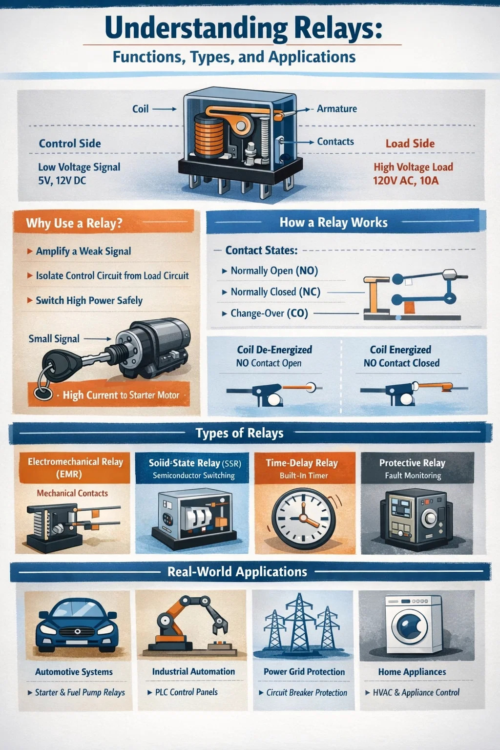
The primary purpose of a relay is to use a small electrical signal to control a much larger electrical load — acting as an electrically operated switch. Instead of running high-voltage or high-current power directly through a control circuit, a relay allows a low-power signal to trigger a separate, high-power circuit safely and remotely. This separation between the control side and the load side is what makes relays indispensable across industries ranging from automotive engineering to industrial automation and home appliance design.
In practical terms, when you turn a key in an older vehicle and the starter motor engages, it is a relay that receives the signal from the ignition switch and closes the high-current circuit to the motor. The ignition switch itself carries only milliamps, while the starter motor may draw 200 amps or more. Without the relay, the ignition switch would need to be built to handle that entire load — which would make it physically massive, expensive, and dangerous to operate.
Beyond switching, relays also serve purposes in signal isolation, circuit protection, time delay functions, and logic operations. Understanding these roles requires looking at how different relay types are constructed and where each fits into real-world systems.
How a Relay Works: The Basic Operating Principle
A conventional electromechanical relay consists of four key components: an electromagnetic coil, an armature (a movable metal strip), a spring, and one or more sets of electrical contacts. When current flows through the coil, it generates a magnetic field that pulls the armature toward it. This movement either closes or opens the contacts in the load circuit, depending on the relay's configuration.
There are two fundamental contact states in a relay:
- Normally Open (NO): The contact is open when the relay coil is de-energized. Current flows through the load circuit only when the relay is activated.
- Normally Closed (NC): The contact is closed by default. The circuit is broken when the relay coil energizes.
- Change-Over (CO) or Double-Throw: The relay switches between two circuits — breaking one connection while making another simultaneously.
The coil voltage required to activate a relay is typically low — commonly 5V, 12V, or 24V DC — while the switched contacts may handle hundreds of volts and tens of amperes on the load side. This voltage disparity is central to the relay's purpose: enabling safe, remote control of powerful circuits.
Solid-state relays (SSRs) operate on a different principle, using semiconductor components such as thyristors, triacs, or transistors instead of mechanical contacts. They achieve switching through optical isolation (using an LED and a photodetector) or transformer coupling, and have no moving parts. This makes SSRs faster, quieter, and more suitable for environments where mechanical wear is a concern.
Core Purposes Relays Serve in Electrical Systems
Amplifying a Weak Control Signal
One of the most fundamental relay purposes is signal amplification in terms of power, not frequency or amplitude. A microcontroller output pin might supply only 3.3V at 20mA — far too weak to directly drive a motor, solenoid, or heating element. A relay bridges this gap: the microcontroller energizes the relay coil with its modest output, and the relay's contacts switch a completely separate high-power circuit. This setup is common in Arduino and Raspberry Pi projects where hobbyists control mains-powered devices through microcontroller logic.
Electrical Isolation Between Circuits
Relays provide galvanic isolation — a complete electrical separation — between the control circuit and the load circuit. There is no direct electrical path between the two sides; energy is transferred only through the magnetic field (in electromechanical relays) or through light (in optocoupled solid-state relays). This isolation is critical in medical equipment, where patient safety requires absolute separation between measurement circuits and power circuits. It also protects sensitive control electronics from voltage spikes and noise generated by inductive loads like motors.
Switching Multiple Circuits Simultaneously
A double-pole or multi-pole relay can switch two or more independent circuits with a single control signal. For example, a double-pole double-throw (DPDT) relay can simultaneously disconnect one motor winding configuration and connect another, enabling motor direction reversal in a single switching operation. This purpose is heavily used in HVAC systems, where a single thermostat signal may need to simultaneously engage a compressor relay and a fan relay.
Time Delay and Sequencing Control
Time-delay relays introduce a deliberate pause between the input signal and the output switching action. They are used in motor control to prevent simultaneous startup of multiple large motors, which would cause excessive current surges on the supply line — a phenomenon called inrush current. For instance, in a factory with ten 50kW motors, staggering startup by 2–3 seconds per motor using time-delay relays prevents the upstream transformer from experiencing a combined 500kW inrush spike. Timing relays also appear in washing machine cycles, traffic light sequencing, and industrial conveyor synchronization.
Protection Against Overloads and Faults
Protective relays monitor electrical parameters such as current, voltage, frequency, and power factor. When a fault condition is detected — such as an overcurrent, undervoltage, or phase imbalance — the protective relay sends a trip signal to a circuit breaker to disconnect the faulty section of the network. In power transmission systems, distance relays measure the impedance between the relay location and the fault point to determine whether a fault is within the protection zone, responding in as little as 20–30 milliseconds to isolate faults before equipment damage occurs.
Types of Relays and Their Specific Purposes
Not all relays are built for the same job. Choosing the right relay type is essential to reliable system performance. The table below summarizes the most common relay types and their primary applications:
| Relay Type | Operating Principle | Primary Purpose | Typical Application |
|---|---|---|---|
| Electromechanical Relay (EMR) | Electromagnetic coil moves mechanical contacts | General switching, isolation | Automotive, home appliances, industrial control |
| Solid-State Relay (SSR) | Optical isolation + semiconductor switching | Fast, silent, high-cycle switching | Temperature controllers, PLC outputs, medical devices |
| Reed Relay | Magnetic field closes reed switch contacts | Low-power, high-speed signal switching | Telecommunications, test equipment, sensors |
| Latching Relay | Bistable — holds state after pulse without continuous power | Energy saving, memory function | Smart meters, remote switching, battery-powered systems |
| Time-Delay Relay | Built-in timer delays contact operation | Sequencing, inrush prevention | Motor starters, HVAC, industrial sequencing |
| Protective Relay | Monitors electrical parameters, trips on fault | Fault detection and isolation | Power grids, transformers, generators |
Where Relays Are Used: Real-World Applications
Automotive Systems
Modern vehicles contain dozens of relays. The main relay controls the fuel injection system, ensuring the engine management unit receives stable power. The starter relay handles the high-current demand of the starter motor. Headlight relays allow the headlight switch — which carries only signal-level current — to switch the full lamp load without overheating. In electric vehicles, contactors (heavy-duty relays) switch the high-voltage battery pack to the drive inverter, handling voltages up to 800V and currents exceeding 500A.
Industrial Automation and PLCs
In industrial control panels, relay modules interface programmable logic controllers (PLCs) with field devices. A PLC output card may supply only 24V DC at 0.5A, but it must control motor contactors, solenoid valves, and indicator lamps that operate at 230V AC. Relay interface modules convert these signals safely. In a typical automotive manufacturing plant, a single assembly line control panel may contain over 200 relays managing everything from conveyor motor starts to robotic welding trigger signals.
Power Grid Protection
Protective relays are the backbone of electrical grid reliability. Overcurrent relays trip circuit breakers when fault currents are detected. Differential relays compare current entering and leaving a transformer — any imbalance indicates an internal fault, causing immediate disconnection. Distance relays on transmission lines can isolate a 400kV fault in under three cycles (approximately 60 milliseconds at 50Hz), preventing cascading failures across the grid. Modern digital relays combine multiple protection functions in a single unit and provide event logging and communications capabilities.
Home Appliances and HVAC
Washing machines use relays to switch the motor between spin and wash directions, to control the heater element, and to operate the water inlet valve. Air conditioning units rely on contactor relays to switch compressors and condenser fan motors on and off under thermostat control. Microwave ovens contain relays that switch the high-voltage transformer circuit. Even dishwashers and refrigerators contain relays to manage compressors, defrost heaters, and water valves — components that require switching currents far beyond what a simple control board can handle directly.
Telecommunications and Signal Routing
Reed relays and small signal relays have long been used in telephone exchanges and signal routing equipment. In automated test equipment (ATE) used to verify circuit boards during manufacturing, banks of reed relays create configurable signal paths between test instruments and the device under test. Reed relays switch in under 1 millisecond and can handle millions of operations before contact wear becomes significant, making them ideal for high-cycle test applications.
Building Automation and Smart Systems
In commercial buildings, relay panels control lighting zones, fire suppression systems, and access control. A building management system (BMS) sends low-voltage digital signals to relay modules that switch 230V lighting circuits for entire floors. Latching relays are particularly useful here — they hold their switched state without continuous coil power, reducing energy consumption in systems that spend most of their time in a fixed state. Smart home systems use relay modules connected to Wi-Fi or Zigbee controllers to retrofit conventional wiring for remote switching of lights, fans, and sockets.
Key Relay Specifications You Need to Understand
Selecting the right relay for an application requires understanding several critical parameters. Using an undersized relay leads to contact welding, overheating, and system failure. Oversizing wastes cost and space. Here are the specifications that matter most:
- Coil Voltage and Current: The voltage required to energize the relay coil reliably, and the current it draws. Common values are 5V, 12V, and 24V DC for control relays, and 24V or 120V AC for industrial contactors.
- Contact Rating (Voltage and Current): The maximum voltage and current the contacts can switch and carry. A relay rated at 10A/250V AC must not be used to switch 15A loads — the contacts will arc excessively and fail prematurely.
- Contact Configuration: Whether the relay is SPST (single pole single throw), SPDT, DPDT, or multi-pole. The configuration determines how many circuits the relay can control and in what manner.
- Operate Time and Release Time: The time from coil energization to contact closure (operate time), and from coil de-energization to contact opening (release time). Standard electromechanical relays operate in 5–15ms; reed relays can operate in under 1ms.
- Mechanical Life and Electrical Life: Mechanical life refers to the number of operations the relay can perform without an electrical load (often 10 million or more). Electrical life is the number of operations under rated load (often 100,000–500,000), which is always lower due to contact arcing.
- Isolation Voltage: The voltage the relay can withstand between the coil and contacts without breakdown. Critical for safety in high-voltage applications and medical equipment — typically 1,500V to 4,000V for general-purpose relays.
- Ambient Temperature Range: The temperature range within which the relay operates reliably. Automotive relays typically must function from -40°C to +85°C or higher.
Electromechanical Relays vs. Solid-State Relays: Which to Choose
Both electromechanical relays (EMRs) and solid-state relays (SSRs) serve the fundamental purpose of electrically controlled switching, but each has strengths and weaknesses that make them suited to different situations.
Advantages of Electromechanical Relays
- Very low contact resistance when closed — typically under 100 milliohms — meaning minimal voltage drop and power loss across the contacts.
- Can switch both AC and DC loads without special consideration.
- Excellent isolation between coil and contacts (galvanic isolation).
- Low cost for general-purpose applications.
- True open-circuit condition when contacts are open — no leakage current through the load.
Advantages of Solid-State Relays
- No moving parts — essentially unlimited mechanical life and silent operation.
- Much faster switching — SSRs can switch in microseconds compared to milliseconds for EMRs.
- No contact bounce, which eliminates the electrical noise spikes that EMR contacts generate during switching.
- Zero-crossing switching (in AC SSRs) reduces electromagnetic interference by switching only when the AC waveform passes through zero voltage.
- Better suited to high-cycle applications — a temperature controller cycling a heater on and off thousands of times per day will wear out an EMR within months but will not affect an SSR.
The main drawbacks of SSRs are their higher cost, the leakage current that flows even when the relay is "off" (a concern with sensitive loads), and the heat they generate — SSRs typically require a heatsink for loads above a few amps due to the voltage drop across the semiconductor output stage (typically 1–1.5V, compared to essentially zero for a clean mechanical contact).
Common Relay Failures and How to Diagnose Them
Understanding the purpose of a relay also means knowing how to identify when one has failed. Relay failures fall into a few distinct categories:
Contact Welding
When a relay switches a load with a very high inrush current — such as a motor starting up or a capacitor bank charging — the arc energy at the contacts can be sufficient to weld them together. A welded relay stays closed even when the coil is de-energized, meaning the load cannot be switched off. This is dangerous in control circuits. Diagnosis: measure voltage across the load terminals with the control signal removed. If full voltage is present, the contacts are welded. Prevention: use a relay with a higher contact current rating or install inrush limiting components.
Contact Pitting and Oxidation
Over thousands of switching cycles, contact surfaces erode and develop pits from arcing. Oxidation on silver contacts can increase contact resistance dramatically, causing voltage drops and overheating. This typically manifests as intermittent operation or the load receiving insufficient voltage despite the relay appearing to operate. Fine-grit contact burnishing can sometimes restore contacts temporarily, but replacement is the correct solution.
Coil Failure
Relay coils can fail due to overvoltage, excessive operating temperature, or simple winding insulation breakdown over time. An open coil means the relay will never energize; a shorted coil causes excessive current draw and may blow the control circuit fuse. Diagnosis: measure the coil resistance with a multimeter. A standard 12V relay coil typically measures 70–200 ohms. An open circuit reading or very low resistance reading (near zero) indicates coil failure.
Mechanical Sticking
In environments with high humidity, corrosive atmospheres, or temperature extremes, the armature mechanism can stick or the spring can lose tension, causing the relay to fail to operate or fail to release correctly. Sealed relay packages are available specifically for harsh environment applications, using hermetically sealed contacts to exclude moisture and contamination.
Best Practices When Using Relays in Circuit Design
Whether designing a simple hobby project or an industrial control system, the following practices ensure relay circuits are reliable, safe, and long-lasting:
- Always use a flyback diode across the coil. When coil current is interrupted, the collapsing magnetic field generates a voltage spike that can reach hundreds of volts and damage transistors or microcontroller outputs driving the relay. A diode placed across the coil in reverse polarity clamps this spike safely.
- Derate contact ratings. For reliable long-life operation, do not load relay contacts beyond 70–80% of their rated current. Full-rated current operation accelerates contact wear significantly.
- Consider the load type. Inductive loads (motors, solenoids, transformers) generate much higher inrush currents and switching transients than resistive loads (heaters, lamps). Use relays rated for inductive loads when appropriate, and consider snubber circuits to suppress arc energy.
- Verify coil voltage supply stability. A relay coil rated for 12V DC may fail to operate reliably if the supply drops to 10V under load. Always ensure adequate supply headroom, especially in automotive environments where battery voltage can drop to 9V during engine cranking.
- Choose the right relay enclosure for the environment. Open-frame relays are unsuitable for dusty or humid environments. Sealed relays or those with dust covers should be specified for all but the cleanest indoor applications.
- Match relay contact material to the load. Silver alloy contacts are standard for general AC switching. Gold-plated contacts are required for very low-current signal switching, where silver oxide film on contacts would introduce unacceptable resistance at signal-level currents below 10mA.